High-Frequency Start Box
Introduction
Welding with a buzz-box (AC arc welder) is much easier if you don't have to scratch-start the arc. A high-frequency start circuit puts a high voltage (AC) in series with the low-voltage high-current welder output. Then, when the welding electrode is brought near the work, the high voltage (HV) ionizes the air and creates a path for the low-voltage and high-current arc.
Sears Roebuck (and probably others) used to sell an add-on box that would add HF start to an ordinary scratch-start welder. Alas, it's no longer available.
The HF start device turns out to be fairly simple. It's easy to build, once you get past acquiring the components, some of which are not commonly available.
Theory of operation
This HF start box consists of a high-voltage source, a radio frequency oscillator, and a transformer to connect the high- frequency high-voltage output so that it is in series with the welder's low-voltage high-current output.
The high-voltage source can be a neon sign transformer. A lighter-weight alternative is a lamp dimmer driving an automotive ignition coil through a motor starting capacitor.
The radio frequency oscillator is the one that Marconi used, back at the beginning of the 20th century. A spark gap acts as an interrupter, and the HV pulses excite an inductor capacitor tank circuit, which resonates at a radio frequency.
The output transformer (the primary of which is the inductor in the RF oscillator tank circuit) couples the high-voltage high-frequency signal to the welder output.
Components selection
The special components are:
- 3uF 400V motor start capacitor for connection between the lamp dimmer and the auto ignition coil.
- 500pF 30kV capacitor for the tank circuit. These are commonly used in high-power radio transmitters, so ham radio parts suppliers are one source for these. The value of this part is highly dependent on the inductance of your output transformer, so if you want to build this, be aware you may have to use a different value here.
- Tungsten spark gaps. There's a place online for these, oddly enough.
- Ferrite core transformer. The core is from an old television yoke. The primary wire is 20kV test prod wire -- 18gauge wire with very thick insulation. The secondary wire is 8gauge wire with 5kV insulation.
Construction
The construction of the line voltage circuitry is straightforward. The high-voltage bits require insulating the circuitry on ceramic or plastic standoffs so that the high voltage will not arc to other circuits. I used teflon bar stock to make insulated standoffs for the spark gap heatsinks.
The DINSE connector used as one of the output connectors needed to be mounted on a plastic insulating sub-panel, as otherwise the high voltage created an arc to the aluminum front panel.
View of output transformer with cover off.
View of spark gap with heat sinking.
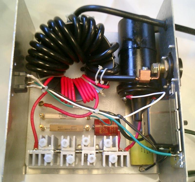
View of circuitry with chassis brace removed.
References
Generating HV with an ignition coil and a lamp dimmer.
Other Acknowledgements
Thanks to the guys who showed up for the October meeting of Make: Princeton for their lively discussion about my difficulties in mounting the spark gaps. Even though we didn't come up with a method at the time, the discussion got me thinking along new lines which eventually resulted in the method I used. This got the project moving again after it had languished for far too long.
Copyright © 2009 William F. Dudley Jr.


 Views
Views